TECHNICAL REFERENCE · OB SUHI 19 · RAVNE NA KOROŠKEM
INFINITE Ravne: Primavest's BMS design and equipment
For the renovation of the apartment building at Ob Suhi 19 in Ravne na Koroškem, Primavest prepared the 2023 control-cabinet and boiler-room controls designs. It installed a control cabinet, PLC, signal modules, relays and an M-Bus interface at the building. The original BMS is operational and has been accepted. The separate fourth-floor BMS upgrade is also operational and has been accepted.
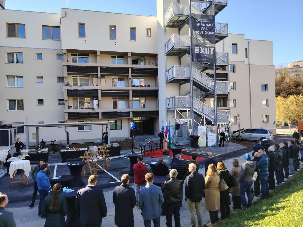
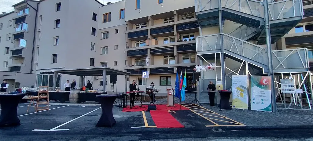
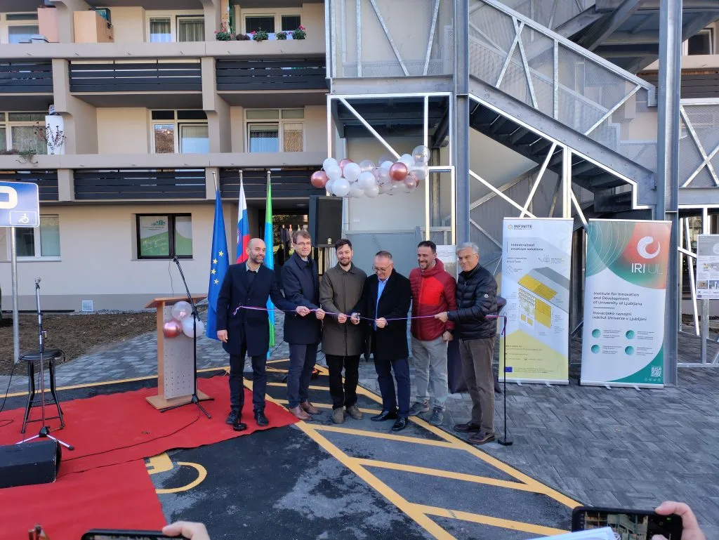
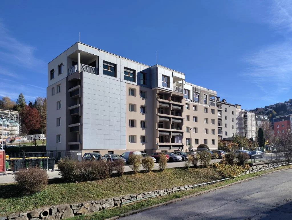
Ob Suhi 19 at its opening2025 · Source: EUTRIPFaçade and external staircase2025 · Source: EUTRIP
PRIMAVEST · BMS DESIGN AND INSTALLATION
Equipment and communications at the building
Primavest prepared the detailed design (PZI) for the BMS control cabinet dated 17 July 2023 and the boiler-room controls design dated 17 November 2023. The designs define the controls, signals and connections for these two scopes.
Primavest installed a powered control cabinet, a PLC controller, digital and analogue signal modules, relays and an M-Bus communication interface for metering data.
01 / POWER SUPPLYControl cabinet
Incoming power, protection and a power supply for the control components.
02 / CONTROLPLC and signals
A controller with digital and analogue inputs and outputs.
03 / SWITCHINGRelays
Relay circuits for connecting control signals.
04 / COMMUNICATIONSM-Bus metering
A serial interface for connecting metering data.
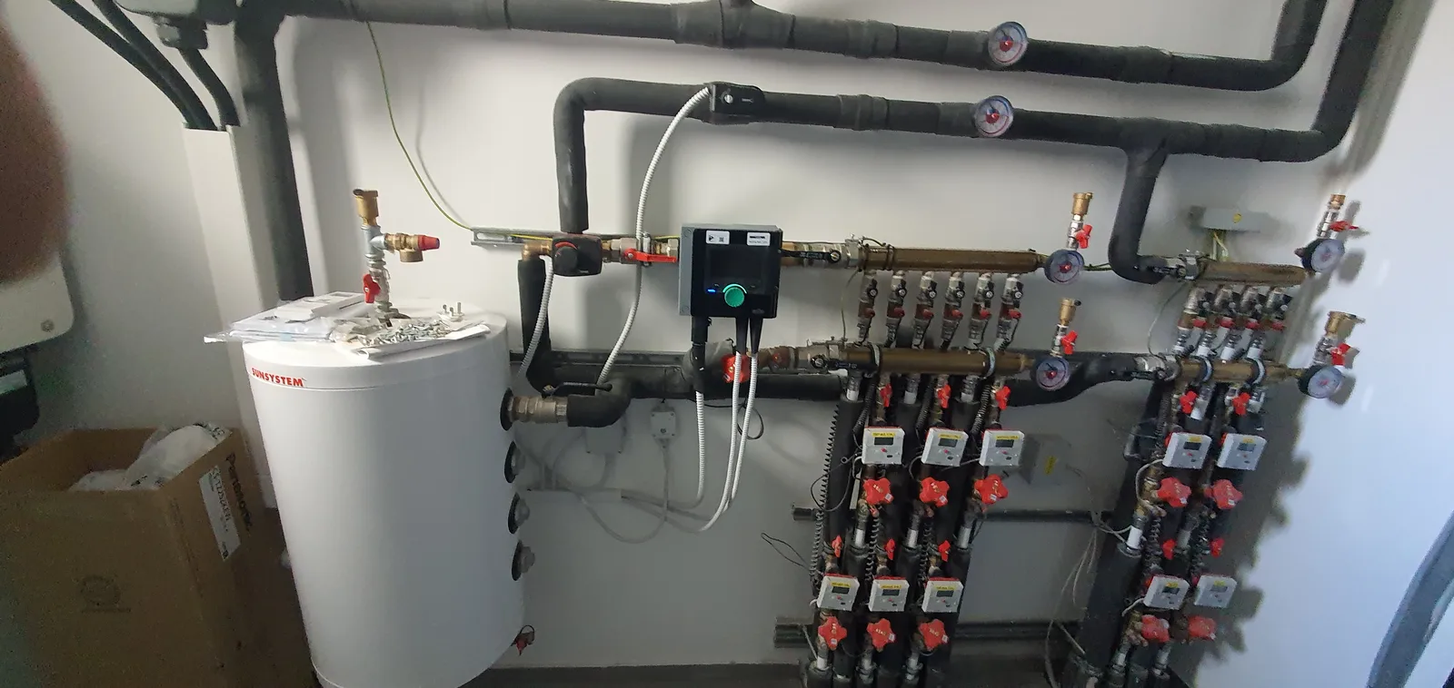
SITE VISIT · JULY 2026Technical room
Heating distribution manifold and pipework in the building.
Source: project archive · 9 July 2026
OB SUHI 19 · TWO TECHNICAL SCOPES
The original BMS and the later upgrade
Two accepted BMS systems are operating at the building: the original building system and the later upgrade for the fourth floor. Primavest designed and installed the original system equipment described below. The new-floor upgrade is a separate project scope.
01 / DETAILED DESIGN · 2023
BMS for the existing building
Primavest's 2023 designs cover the BMS control cabinet and boiler-room controls. For this scope, Primavest installed a powered control cabinet, PLC, signal modules, relays and an M-Bus interface. The original BMS is operational and has been accepted.
Control and monitoring of the heating circuits.
Connections to the heat pump, district heating and domestic hot-water system as described in the project schedule.
Acquisition of control signals and metering data in the BMS.
02 / UPGRADE · FOURTH FLOOR
New residential units
Separate BMS upgrade documents cover the new floor with six apartments. The device inventory and topology describe metering points, room data and communications to the management system. This system is also operational and has been accepted.
Cold- and hot-water meters, electricity meters and heat meters for heating and ventilation.
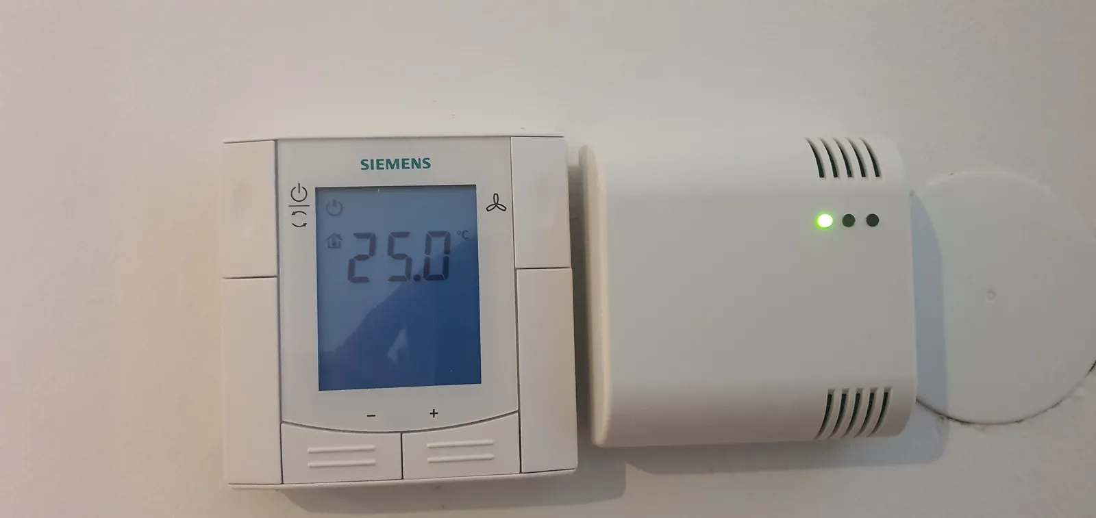
Room thermostats and sensors for temperature, relative humidity and CO₂.
Ventilation units and M-Bus or Modbus connections.
6
apartments with separately metered heating energy
2
control circuits: underfloor heating and ventilation units
4
larger ventilation units in addition to local heat-recovery units
Technical data for the added floor is based on the building optimisation report from 2026.
ORIGINAL BMS · 2023 DETAILED DESIGN
Model references in the control-cabinet design
The original BMS schematic identifies the controller, signal module, communication interface and power supply by model.
PLC controller
Saia PCD1.M2110R1
Analogue input/output module
Saia PCD2.W525
Serial M-Bus interface
Saia PCD2.F2710
24 V power supply
Mean Well HDR-30-24
ROOFTOP EXTENSION · FINAL STATEMENT 2026
Billed thermostats and heat meters
The rooftop-extension contractor's final statement bills the underfloor-heating equipment and heat meters separately. The BMS device list sets out the metering-point allocation and communications.
Underfloor-heating room thermostats
20 units · final statement
Compact heat meters
10 units · final statement
BMS metering-point allocation
6 for underfloor heating · 4 for ventilation
Communications in the BMS device list
M-Bus · Modbus
Two separate scopes: the first section describes Primavest's installed control equipment. Extension quantities come from the contractor's final statement; the metering-point allocation and communications come from a separate BMS device list.
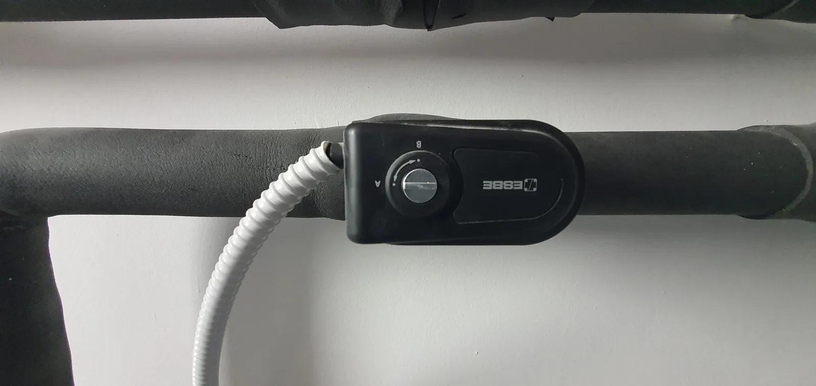
SITE VISIT · JULY 2026Motorized actuator on a pipe
Site photograph of a device in the building's technical room.
Source: project archive · 9 July 2026
UPGRADE DESIGN · 2025
From meter to management system
The BMS design for the fourth floor dated 21 February 2025 shows a separate control and communications system for the new level. It links metering points, room sensors, ventilation, shading and photovoltaics through M-Bus, Modbus and Ethernet.
CABINET · DESIGN REFERENCES
Control and communications
The design shows protected incoming power, a 24 V supply, digital inputs for switches, digital outputs and relays for blinds, and interfaces for metering and serial data. The models in the table are design references.
Power supply
Mean Well NDR-120
Digital inputs
Saia PCD1.E1000-A10
Digital outputs
Saia PCD1.A1000-A20
M-Bus metering
Solvimus gateway
Serial connections
tGW-715 RS-485/Ethernet gateways
Network connection
Ethernet switch
NEW FLOOR · CONNECTION DESIGN
Meters and building equipment
The drawing identifies the metering points and equipment included in the BMS design. These are design quantities, not a list of confirmed installations.
Electricity
10 electricity meters in the design
Heat energy
10 CF Echo II meters in the design
Domestic water
Cold- and hot-water meters
Indoor conditions
6 room sensors for temperature, humidity and CO₂
Ventilation
4 Vortice units; heat-pump connection
Shading
Blind switches, relays and motors
Photovoltaics
Roof and façade inverters; solar-irradiance sensor
This drawing describes the planned 2025 upgrade. Primavest's 2023 control-equipment installation is presented separately above.
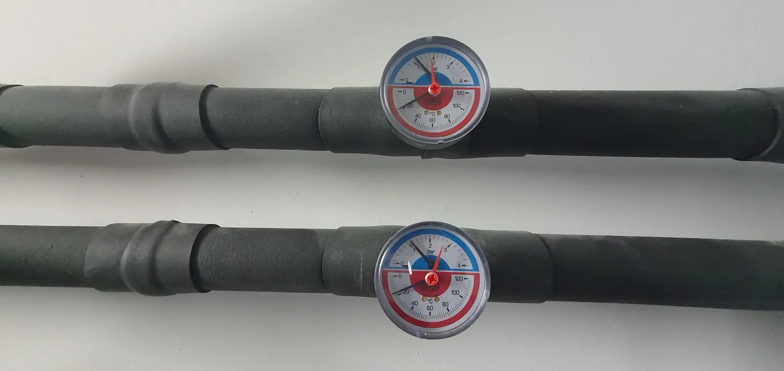
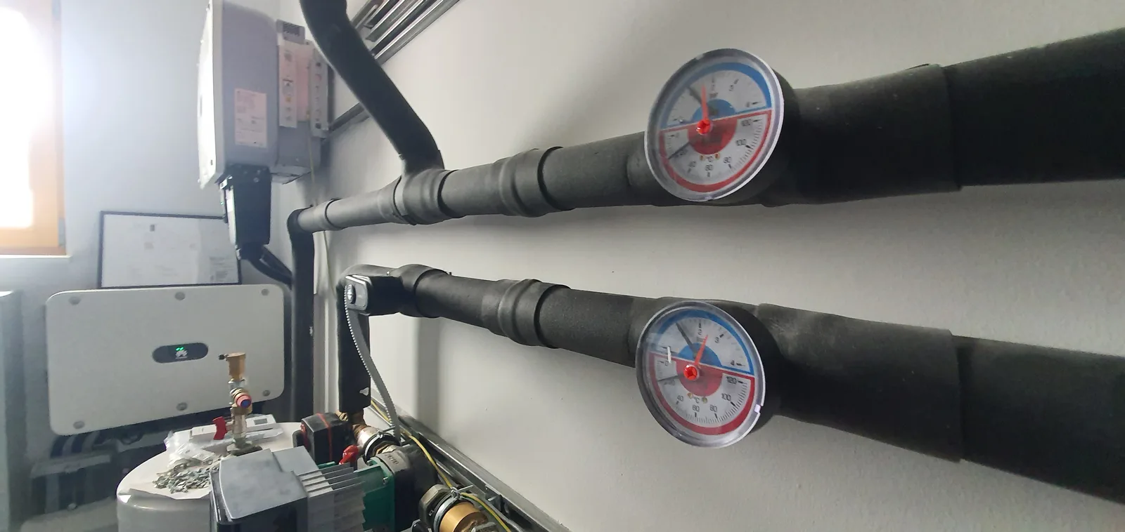
SITE VISIT · JULY 2026Measuring instruments on the pipes
Two analog measuring instruments in the technical room.
Source: project archive · 9 July 2026
INFINITE · THE WIDER PROJECT
How the building changed
The renovation combines a new building envelope, energy systems and an additional floor. The following features describe the INFINITE project as a whole.
01 · ENVELOPE
Prefabricated façade
Part of the south façade uses prefabricated elements with integrated photovoltaics. The other façades received additional thermal insulation.
02 · ENERGY
Heat and electricity
Heat pumps provide heating and domestic hot water, while the existing district heating remains a backup source. Photovoltaic panels are installed on the roof.
03 · SPACE
An additional floor
The additional floor added six apartments to the building. It includes ventilation, shading and indoor-comfort features.